Advanced Computer Engineering
CS/ENGR 433
Team Members –
Project Objectives –
To assemble a preordered robot kit, observe its movements and mimic its responses using a Matlab simulator.
Robot – The
robot kit was purchased from Mondotronics
at 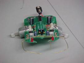 a
cost of $49.95. The robot is Cybug
Artificial Lifeform Kit. It features
photoelectric cells to either seek or avoid light, and bump switches so it
could avoid obstacles. Its design can
be seen to be symmetrical, meaning that both sides (i.e. motor and sensors) are
independent of each other.
a
cost of $49.95. The robot is Cybug
Artificial Lifeform Kit. It features
photoelectric cells to either seek or avoid light, and bump switches so it
could avoid obstacles. Its design can
be seen to be symmetrical, meaning that both sides (i.e. motor and sensors) are
independent of each other.
The overall design of the robot was pretty simple, plug and solder. All functionality is hard wired, therefore there is no “brain” or microcontroller. This makes behavior modifications to the robot quite difficult.
The designs for the motor attachment and wheel material were found to be quite lacking. The motors were to be soldered onto a wire stretched across a cutout in the board. However, we found that solder does not stick to this wire. This causes the motors to be at an angle greater than the specified 45-degree angle. Also the wheels included in the kit are nothing but a slice off of a glue stick.
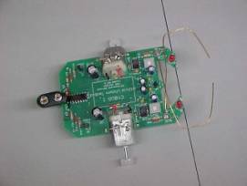 While the instructions for assembly were
very implicit, certain details were confusing and sometimes cryptic. One occurrence was for the photoelectric
sensors. The fact that they must be
angled forward was somewhat buried after the instruction to solder them. Because of this the robot only senses light
directly above it. Also the wiring for
ground has a break in for the sole purpose of an on/off switch. If an on/off switch is not used, this break
must be soldered together. This also
was buried within the instructions.
While the instructions for assembly were
very implicit, certain details were confusing and sometimes cryptic. One occurrence was for the photoelectric
sensors. The fact that they must be
angled forward was somewhat buried after the instruction to solder them. Because of this the robot only senses light
directly above it. Also the wiring for
ground has a break in for the sole purpose of an on/off switch. If an on/off switch is not used, this break
must be soldered together. This also
was buried within the instructions.
 By observing the movements of the robot
an algorithm was derived to mimic the robot.
This then was used to code a simulation of the robot tracking a target
and avoiding obstacles. This was done
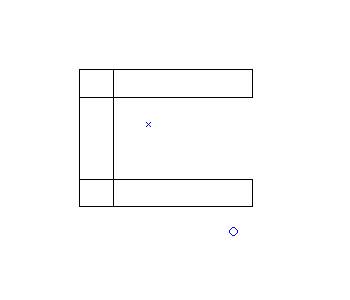
using Matlab, which uses a language similar to C. First a ‘maze’ was setup in a sideways U shape with the robot
(‘o’) located outside of the U and the target (‘x’) located within the U.
By observing the movements of the robot
an algorithm was derived to mimic the robot.
This then was used to code a simulation of the robot tracking a target
and avoiding obstacles. This was done
using Matlab, which uses a language similar to C. First a ‘maze’ was setup in a sideways U shape with the robot
(‘o’) located outside of the U and the target (‘x’) located within the U.
First, a vector is found between n the target and the robot. This gets the direction to the robot. From this, the length of the vector is found and the vector is divided by its length. This results in a vector of length one (a unit vector). A user-defined constant is assigned to the velocity. The constant used for this simulation was 0.1. The velocity is multiplied with the unit vector, which is added to the robots position effectively moving the robot.
To simulate collision detection, a small square was invisibly placed around the robot. The coordinates of the four corners were checked to see if they were contained within the boundaries of the rectangles. If a collision is found the robot is assigned a new position back one step and to the right one step. In this way, the robot always turns right. After this move the robot continues on its normal course.
While this simulation is close to mimicking the robot it is not exact. Because the robot has two independent sides each side should be calculated separately. When one side moves the other side is held constant. This results in movement around an arc.
Possible Improvements -
The collision detection was written for the robot to always start at the bottom. Meaning that the robot always moves down one and to the right one in the coordinate system. This can cause problems if the robot hits any wall other than the bottom. As this simulation is improved, collision detection for any side of the wall will be added.
A feature of allowing the user to select the starting position of the robot and the target, as well as inputting the starting velocity will be added for the next revision.