Elizabethtown College Syllabus
DIGITAL
CIRCUITS AND COMPUTER INTERFACING
“Digital Design II, Assembly Language, and Interfacing”
EGR/CS 333
Spring,
2019
Advanced digital logic design and circuit implementations; assembly language programming; design, testing, and construction of interfaces; design and testing of supporting software. Also programming and interfacing with common industry controllers, such as Programmable Logic Controllers (PLC’s). Hours: lecture 3, laboratory 3. Prereq: CS 122 & 332,. Spring semester, odd numbered years.
Professor: Joseph T Wunderlich PhD
Associate Professor of Engineering and Computer Science
Computer Engineering Program Coordinator
Architectural Studies Program Coordinator
Offices: E284E, E273
Office: 717-361-1295 Cell: 717-368-9715
Email: wunderjt@etown.edu
Website: http://users.etown.edu/w/wunderjt
Office Hours & Calendar:http://users.etown.edu/w/wunderjt/schedules/CALENDAR3_s19_web.htm
Meeting Times
We meet 300 minutes per week (as expected for 6 contact-hours);
MF 3:30-6:00, but we will substitute a few hours for special events to be announced.
Course Credit: 4
Contact Hours: 6 (therefore 6 x 50 = 300 minutes per week of “contact”); Typical weekly distribution:
· 120 minutes of Lecture
· 120 minutes of Lab
· 60 minutes of Studio for combined lecture/lab/presentations/etc.
Course Objectives
1. Hardware and software design for interfacing
2. Assembly language programming
3. Advanced digital circuit design
4. Breadboard circuit implementations
5. Programmable Logic Controllers (PLC’s) implementations
6. Field Programmable Gate Arrays
7. Raspberry Pi’s
8. Simulation Software Engineering vs. Real-time Code Development
Prerequisite Topics
1. Intermediate programming skills (from CS122)
2. Introduction to assembly language programming (from EGR/CS332)
3. Computer architecture (register-transfer level data-flow), (from EGR/CS332)
4. Computer architecture (gate-level data-flow and control), (from EGR/CS332)
5. Combinational digital circuit design, (from EGR/CS332)
6. Sequential digital circuit design, (from EGR/CS332)
Grading
· 50% Laboratory projects
· 20% Midterm exam(s)
· 30% Comprehensive final exam
COURSE GRADE:
(60-62)=D-,
(63-67)=D, (68-69)=D+, (70-72)=C-, (73-77)=C, (78-79)=C+, (80-82)=B-,
(83-87)=B, (88-89)=B+, (90-92)=A-, (93-100)=A
(with any fractional part rounded to
the nearest integer)
Attendance Policy: , 2019 Manual developed by TA during semester
Since this course requires much team activity, there will be minus one full course percentage point for any unexcused absence;. however, do not come to class sick! (Else minus variable points depending on severity of illness)
Course Texts, Manuals, and Readings Reading Packet must be purchased from bookstore; excerpts from all of the below will be included or handed out in class
1. Frank D. Petruzella, “Programmable Logical Controllers,” 4th edition, September 3, 2010, McGraw-Hill Science/Engineering/Math, (ISBN: 0073510882).
2. Arijit Saha and Nilotpal Manna, “Digital Principles and Logic Design,” 1st edition, January 28, 2009, Jones & Bartlett Publishers, (ISBN: 978076377373). This is the text used for prerequisite course EGR/CS332
3. Kenneth Ayala, " 8051 Microcontroller: Architecture, Programming and Applications," 2 edition, September 26, 1996 – this one is much better than the newer editions), Delmar Learning, (ISBN: 9780314201881).
4. Our LAB-MANUAL & TUTORIAL: 2018 IC's, Circuit Trainer, and Power Supply
5. Our LAB-MANUAL & TUTORIAL: 2018 NanoPLC's
6. Our LAB-MANUAL & TUTORIAL: 2018 Advanced PLC's (2017)
7. Our LAB-MANUAL & TUTORIAL: 2018 FPGA's (2018a, 2013, pre-2013, 2019 Manual developed by TA during semester)
8. Our LAB-MANUAL & TUTORIAL: 2015 Intel Microcontrollers (2014, Pre-2013, 2019 Manual developed by TA during semester)
9. Our LAB-MANUAL & TUTORIAL: 2017 Rasberry Pi and ARM Microcontrollers
Course Outline
I. Review and continuation of Discrete Math for Digital Design (continuation of CS/EGR 332)
II. Review and continuation of Digital Design
1. Combinational Digital Circuit Design (continuation of CS/EGR 332 topics)
2. Sequential Digital Circuit Design (continuation of CS/EGR 332 topics)
III. Electronics
1. Resistors (Part 1) (Part 2)
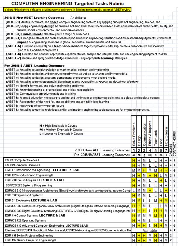
2. Debouncing Switches (waveform analysis 1) (waveform analysis 2)
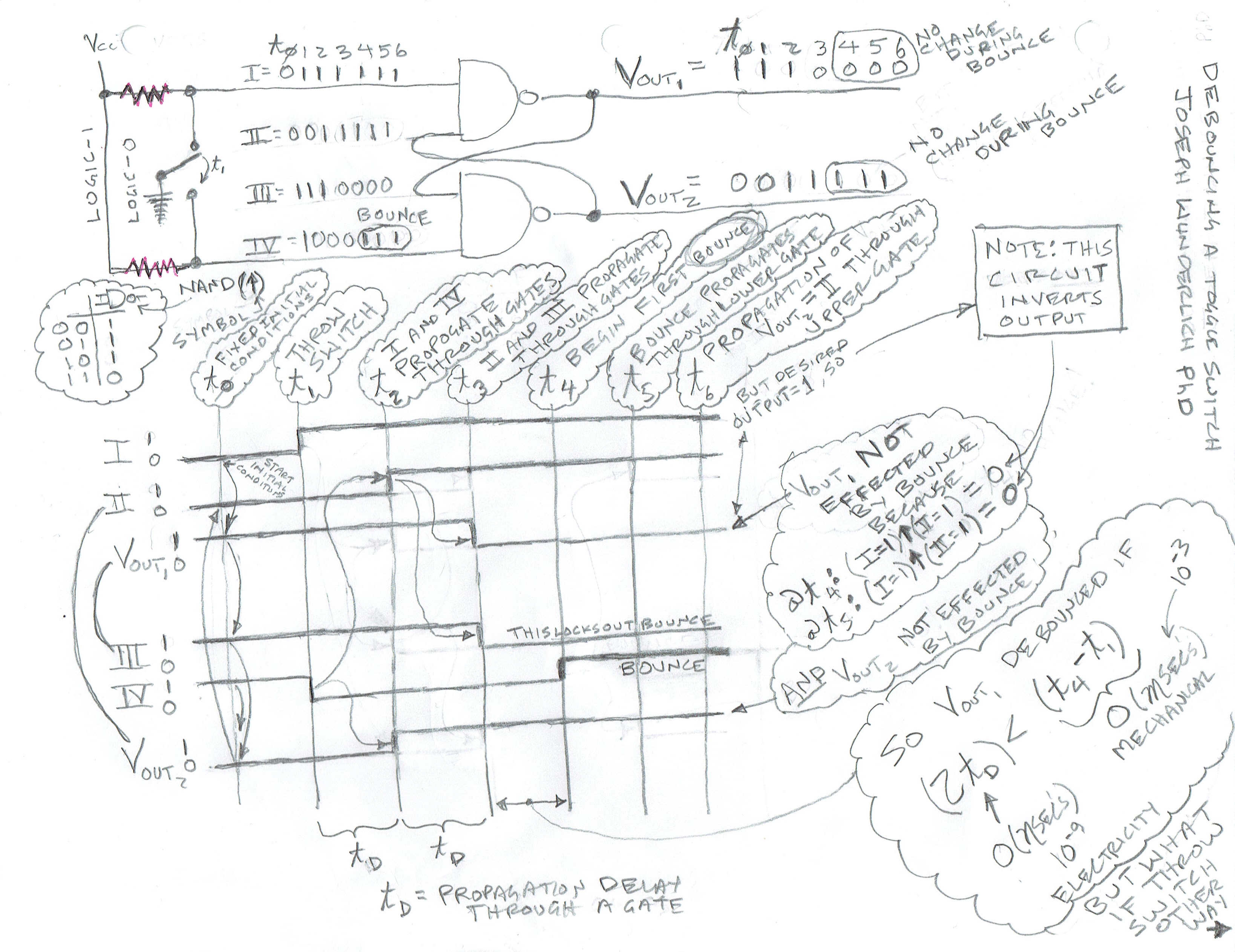
3. Relays by A.Offner
4. Buffers
5. Fan-out, Floating pins, Pull-up resistors, etc.
6. CMOS vs. Bipolar TTL circuits
7. Various chip characteristics
8. LAB-MANUAL & TUTORIAL: 2018 IC's, Circuit Trainer, and Power Supply
IV. PLC's (Programmable Logic Controllers)
a) Traditional Ladder logic
b) Modern Methods
2. Phoenix Contact PLC’s
a) LAB-MANUAL & TUTORIAL: 2018 NanoPLC's (TTL to NanoLC VIDEO)
· Hardware
· Software Development (using flow-charting software)
· Design
· Testing and debugging
b) LAB-MANUAL & TUTORIAL: 2018 Advanced PLC's (2017)
· Hardware
· Software Development (using high level language)
· Design
· Testing and debugging
V. Field Programmable Gate Arrays (FPGA’s)
1. LAB-MANUAL & TUTORIAL: 2018 FPGA's (2018a, 2013, pre-2013, 2019 Manual developed by TA during semester)
a) Hardware for Digital Design
b) Software Development (using “HDL” Hardware Descriptive Language”)
c) Design
d) Testing and debugging
VI. Communications (PDF) (PPT)
1. Packetized
2. Serial vs. Parallel
3. UART
4. Overcoming the Inter-Processor Communication (IPC) bottleneck
VII. Simulation vs. Real-Time Control
1. Wunderlich Factory Real-Time Control of a Bottling Plant
2. Wunderlich Factory Simulation of a Bottling Plant
3. Wunderlich publication on Simulation vs. Real-Time control
VIII. Microcontrollers vs. Microprocessors
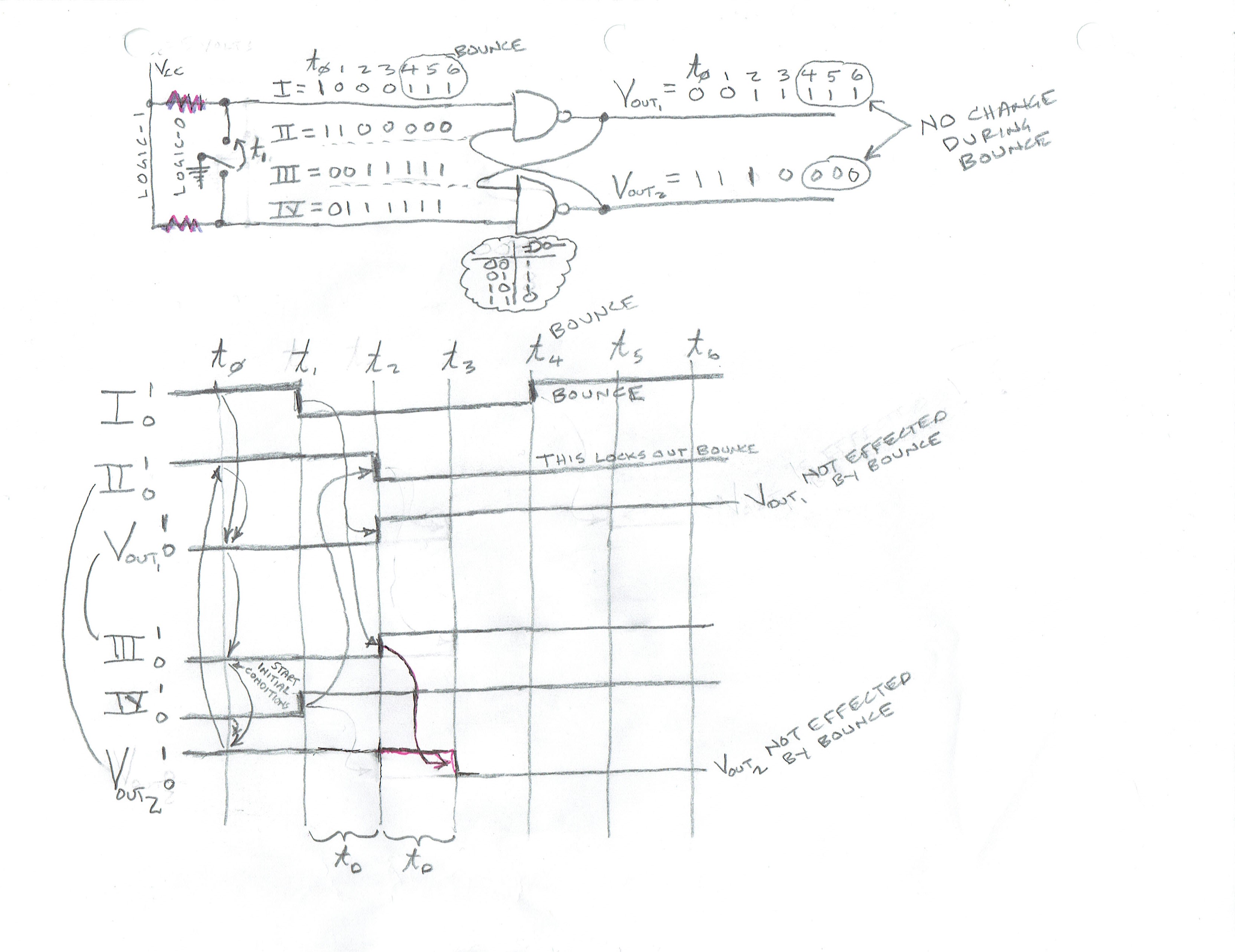
1. Instruction sets, Register sets, Instruction formats, Pin-outs, Memory maps, Number ranges and precision
2. Wunderlich publication on Microprocessors vs Microcontrollers (emphasis on code)
IX. Assembly Language Programming
1. Programming in Intel 8051 and 80251 Microcontroller Assembly language
a) Case Studies
b) Simulations and Development Systems
c) Software Engineering of Real-Time Code
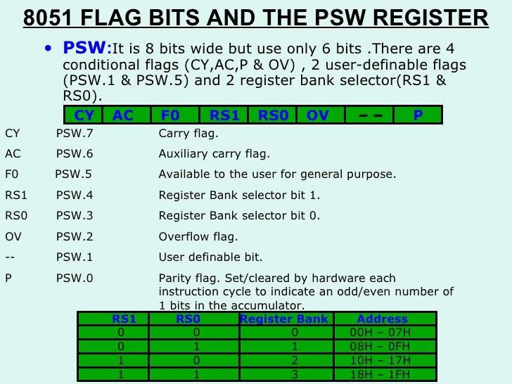
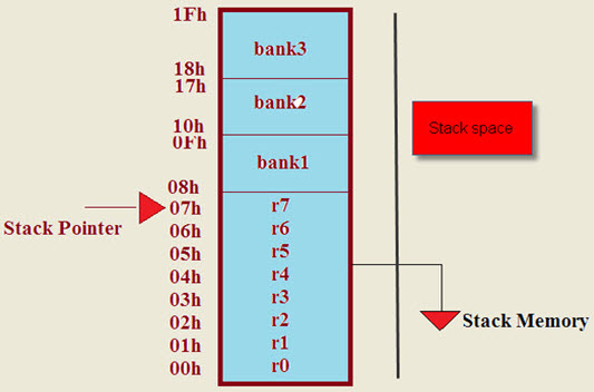
d) Memory Map, PSW, Stack, Instruction Set(1,2), 8051Jumps&Calls, 80251Jumps&Calls
e) LAB-MANUAL & TUTORIAL:
· 2015 Intel Microcontrollers (2014, Pre-2013, 2019 Manual developed by TA during semester)
2. Programming in ARM Microcontroller Assembly language
a) LAB-MANUAL & TUTORIAL: 2017 Rasberry Pi and ARM Microcontrollers
b) Case Studies
c) Simulations and Development Systems
d) Software Engineering of Real-Time Code
Disabilities
Elizabethtown College welcomes otherwise qualified students with disabilities to participate in all of its courses, programs, services, and activities. If you have a documented disability and would like to request accommodations in order to access course material, activities, or requirements, please contact the Director of Disability Services, Lynne Davies, by phone (361-1227) or e-mail daviesl@etown.edu. If your documentation meets the college’s documentation guidelines, you will be given a letter from Disability Services for each of your professors. Students experiencing certain documented temporary conditions, such as post-concussive symptoms, may also qualify for temporary academic accommodations and adjustments. As early as possible in the semester, set up an appointment to meet with me, the instructor, to discuss the academic adjustments specified in your accommodations letter as they pertain to my class.
Class Cancelation
Any non-emergency class cancelation will be announced via email at least a two hours before class time, in addition to signage posted by Department Administrative Assistants. Any makeup work will be announced to insure all intended course content is covered.
Religious Observations
The College is willing to accommodate individual religious beliefs and practices. It is your responsibility to meet with the class instructor in advance to request accommodation related to your religious observances that may conflict with this class, and to make appropriate plans to make up any missed work.
Academic Honesty
Elizabethtown College Pledge of Integrity: "Elizabethtown College is a community engaged in a living and learning experience, the foundation of which is mutual trust and respect. Therefore, we will strive to behave toward one another with respect for the rights of others, and we promise to represent as our work only that which is indeed our own, refraining from all forms of lying, plagiarizing, and cheating." See the 2016-17 Elizabethtown College Catalog, “Standards of Academic Integrity” (Academic Integrity at Elizabethtown College, 11th ed. (https://www.etown.edu/offices/dean-of-students/files/academic-integrity-handbook.pdf).
LABS
IF LABS ARE BUILT (AND POSSIBLY REBUILT), BUT DON'T FULLY FUNCTION: For demonstrations and reports, deduct depends on how adequately you identify problems. For example, make test set-ups to verify functionality of isolated simulation sub-parts, chips, circuit trainer elements, software, relays, other electronics, motors or other higher-voltage circuits and devices. PROVE THAT NO EASY FIX OR SUBSTITUTION WAS POSSIBLE or EASILY IDENTIFIABLE AT THE TIME. Discuss (1) How you identified problems, and (2) How you tried to fix them. Include evidence that you fully understand and have properly connected all pins on a given chip (including considering floating-pins, powering the chip, needed pull-up resistors, proper voltage levels, etc.), and that you have exhausted much time attempted to solve all problems).
REPORTS must include:
· PHOTO’S OF ALL CIRCUITS (AND TEST-SET-UP’S BUILT)
· Title Page with lab number, name of lab, your names, Majors, Year (e.g., Junior), who is demonstrating, and who is the designated TEAM LEADER
· Sections numbered and tilted as follows (always list all of these, and simply put “NA” if not applicable):
1. “Assignment” (An exact copy of everything in this document -- exactly how it looks here)
2. “Equipment Used” (A list of hardware and software) INCLUDE PHOTO’S OF ALL EQUIPMENT
3. “Methodology” (including all design steps, analysis, DECISIONS MADE, etc.) INCLUDE PHOTO’S OF ALL CIRCUITS BUILT
4. “Options” (if applicable, a comparison of each method used)
5. “Problems Encountered” (including any debugging methodology) INCLUDE PHOTO’S OF ANY TEST-CIRCUITS BUILT
6. “Testing Methodology” (including timing traces, test-vectors, and RATIONALE FOR HOW YOUR METHODOLOGY ASSURES QUALITY) including estimated probability of satisfactory coverage by chosen test vectors
7. “References” (in standard IEEE format)
8. “Appendices” (for spec sheets, etc.)
· ALL DESIGN PROCESS STEPS MUST BE INCLUDED for Digital Logic designs (NUMBERED as in EGR/CS 332). If design step not done, list as “N.A.”
For Combinational Digital Logic Design:
Step 1: Define problem
Step 2: Encode variables
Step 3: Create truth table
Step 4: Find simplified function(s)
Step 5: Draw logic circuit
Step 6: Convert to NAND’s
Step 7: Check assumptions
Step 8: Chip circuit diagram
For Sequential Digital Logic Design::
Step 1: Define problem
Step 2: Create state diagram
Step 3: Encode variables
Step 4: Minimize machine
Step 5: Create state table
Step 6: Append flip-flop inputs
Step 7: Find simplified function(s)
Step 8: Draw logic circuit
Step 9: Convert to NAND’s
Step 10: Analyze any unused states
Step 11: Revise state diagram
Step 12: Check Assumptions
Step 13: Chip circuit diagram
· COLOR-CODED LOGIC DIAGRAMS are required for any digital circuit (Breadboard, FPGA, etc.)
· COLOR-CODED CIRCUIT SCHEMATICS are required for any circuit implemented (Breadboard, PLC, ladder logic, etc.), color is a must, hand-colored is ok
· FLOW CHART is required for any program
· COMMENT EVERY LINE OF CODE
· TEAM LEADER has responsibility of coordinating all equipment problems and acquisition of needed parts. Try to stick with same person for this role.
DEMONSTRATIONS
Alternate team members demonstrate lab to me (partners must be present). We do this for previous week’s assignment while you begin the next assignment
GRADING for both demonstrations and reports, a 92 is for everything done very well and professional; to get more points, enhance things in creative way
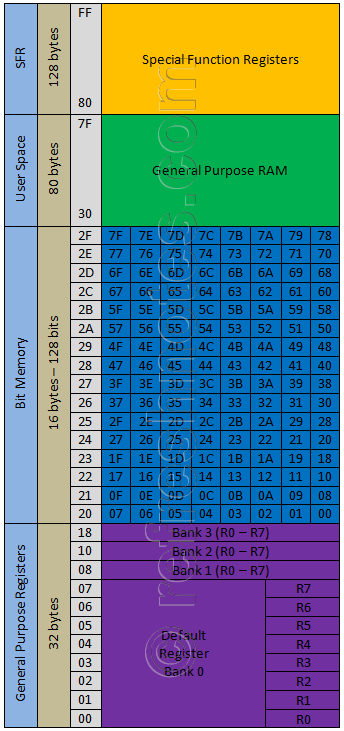
Learning Outcomes
![]()